Representation of an accelerometer Circuit Diagram
BlogRepresentation of an accelerometer Circuit Diagram combines a three axis ADXL335 accelerometer with a two axis IDG500 gyroscope. For now we'll just use the accelerometer. A three axis accelerometer detects linear accelerations in three perpendicular directions. If it helps, picture a ball inside a box with pressure sensitive walls. As you shake the box around, the ball presses Accelerometers and gyro sensors are both used to detect motion, but they measure different aspects. Accelerometers. Accelerometers measure linear acceleration experienced by an object. They detect acceleration when an object transitions between a stationary state and a moving state, or changes direction or speed.
-This is the primary sensor used to sense motion. It only detects accelerations of approximately 3g's. However, this should be enough for the scope of this project. In order to detect motion, the accelerometer values will have to exceed the max or min value for the idle state. Lastly, the code tells the user that the calibration is finished
Make It Shake, Rattle, and Roll: Accelerometer Use Circuit Diagram
The accelerometer we will use is the MMA8452Q, manufactured by Freescale. to detect motion, separate analog-to-digital conversion, and various support hardware. Sparkfun's Accelerometer Breakout Hookup Guide does a great job of describing how to hook up the accelerometer in general (see below). It also provide a nice set of example 🔸New component Accelerometer . Overview. The accelerometer, aka 3-axis accelerometer, measures accelerations, changes of velocity with time, and the direction of movement of an object on x, y, and z-axis.It can detect changes in motion, including vibration, rotation, and changes in linear acceleration.They can also detect the direction and magnitude of gravitational forces acting on the object.
Motion tracking sensors are used in applications like robotics, gesture recognition, vehicle stabilization, position control in drones/quadcopters, pointing devices, game controllers, and fitness tracking devices. One of the popular motion tracking sensors is MPU6050. It is a six-axis MEMS motion tracking sensor that includes a MEMS accelerometer and a MEMS gyroscope. The sensor also has…

PDF 1. Sensing your orientation: how to use an accelerometer Circuit Diagram
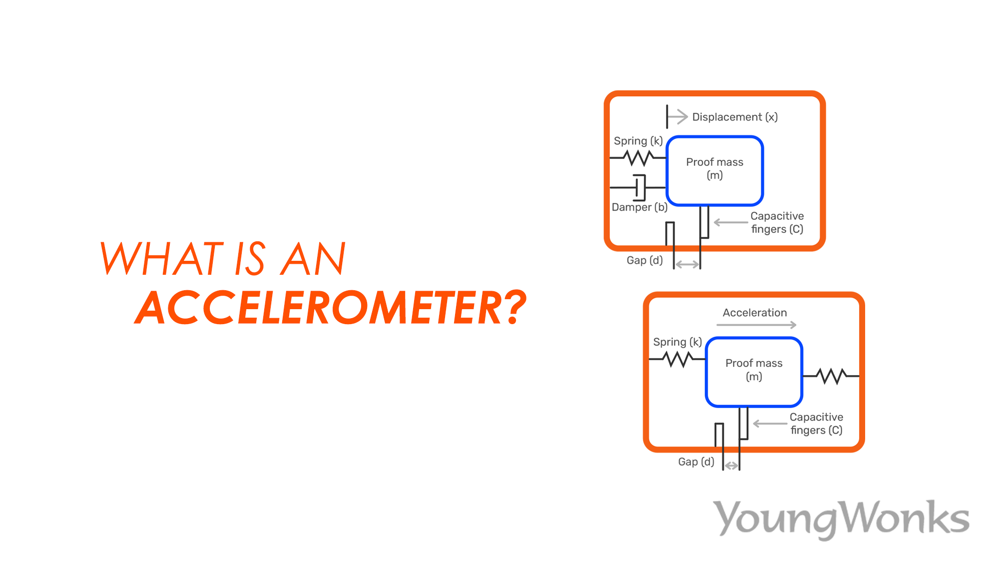
An accelerometer is a device that measures acceleration forces, such as gravity and motion, by converting them into electrical signals. These devices are used in various technologies, including smartphones for orientation detection and vehicles for stability control. The accelerometer may be used in other ways too - for example, it can be used to detect any device motion. Then the values of the X, Y and Z axis motion can be converted, using math, into angles, magnitude of the movement, and other values.